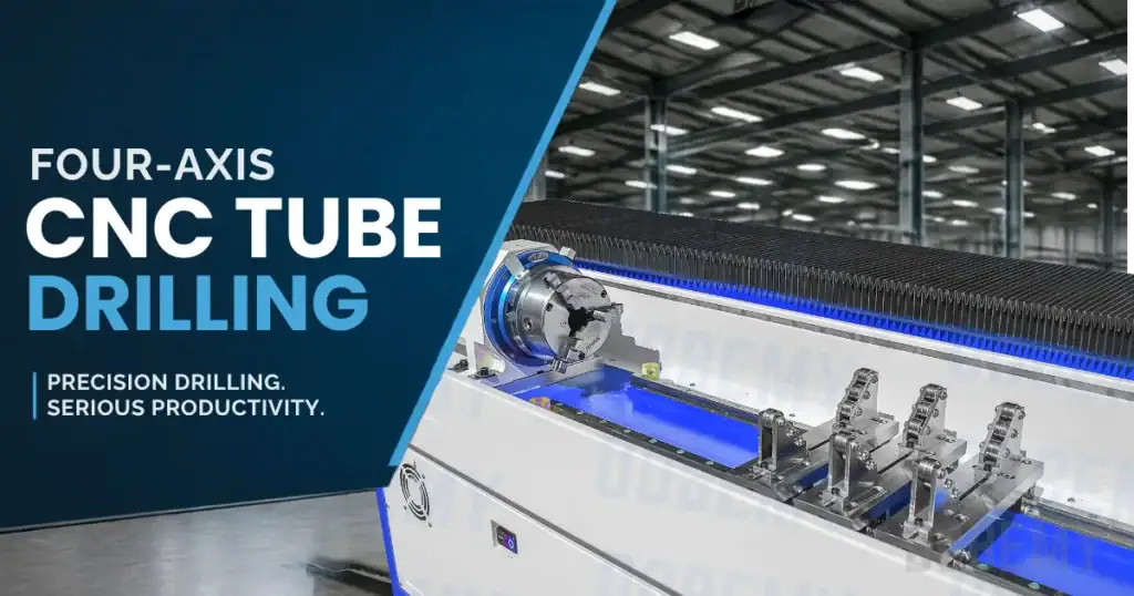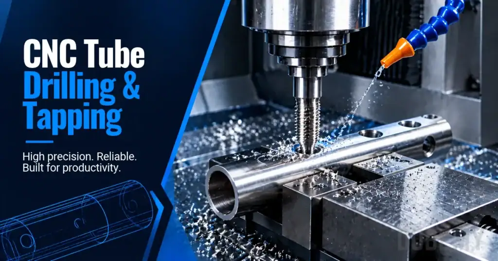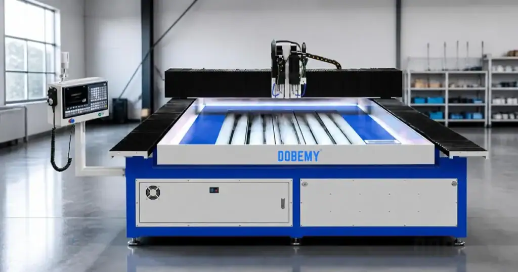


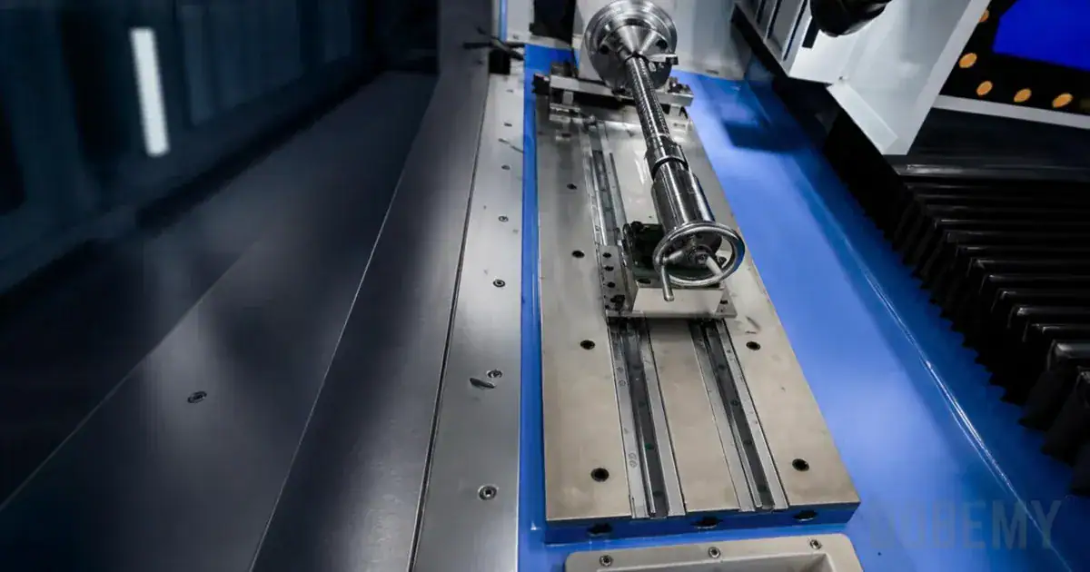
Selecting the right tube drilling machine fixture determines whether your production runs smoothly or struggles with part movement, distortion, and inconsistent hole positions. Round tubes present unique challenges with their tendency to roll, while square tubes offer flat surfaces but still demand proper restraint against drilling and tapping forces.
Key Takeaways
- Round tubes need anti-rotation restraint and V-blocks or shaped supports to prevent rolling during drilling
- Square tubes offer flat clamping surfaces but still require proper support to resist cutting forces
- Thin-wall tubes need controlled clamping force and possible internal support to prevent distortion
- Fixture selection depends on tube geometry, hole pattern, production volume, and machine interface requirements
- Proper axial stops and datum surfaces ensure repeatable hole positioning across production runs
Manufacturing engineers face critical decisions when setting up tube drilling operations. The fixture must accommodate your specific tube shapes and sizes while providing secure workholding without crushing thin walls. Whether drilling straight holes, angled holes, or preparing for tapping operations, the fixture design directly impacts part quality and production efficiency.
Understanding Tube Drilling Fixture Requirements
Related guidance: CNC drilling and tapping equipment.
Tube drilling fixtures serve three essential functions: locating the tube in the correct position, supporting it against cutting forces, and clamping it securely without causing distortion. Each tube geometry presents unique challenges that influence fixture selection.
Round tubes require fixtures that prevent both rotation and linear movement. The cylindrical surface offers no natural reference points, making precise location more challenging than with flat-sided stock. V-blocks provide the traditional solution, creating two contact lines that center the tube while allowing consistent positioning.
Square and rectangular tubes simplify some aspects of fixturing through their flat surfaces. These profiles provide clear reference surfaces for location and resist rotation more readily. However, they still require proper support along their length and firm clamping to resist drilling torque and feed forces.
Wall thickness significantly impacts fixture design requirements. Thick-walled tubes withstand higher clamping forces without distortion, allowing simpler fixture designs. Thin-walled tubes demand careful force distribution and may require internal mandrels or expanding supports to prevent crushing or ovalization during clamping.
Fixture Types for Round Tube Drilling
V-Block Fixtures
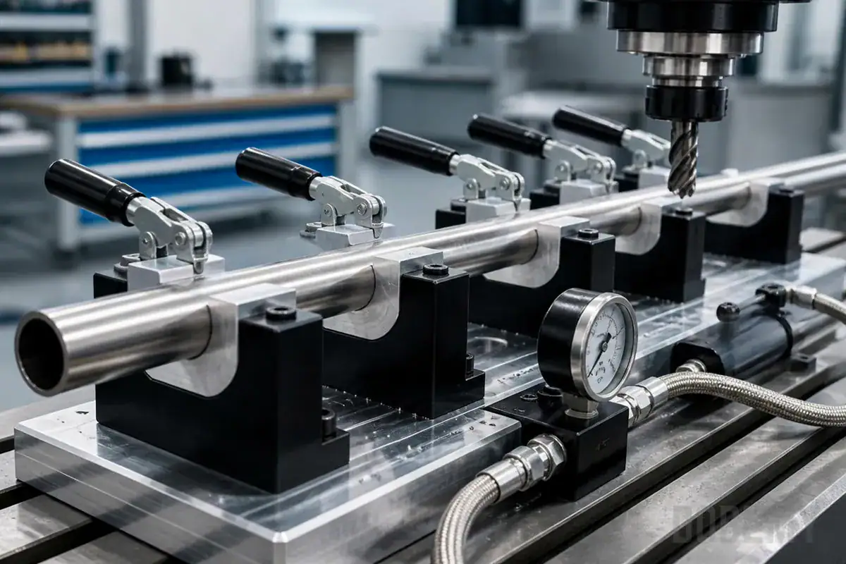
V-blocks remain the most common fixture type for round tube drilling operations. The V-shaped groove automatically centers cylindrical stock while providing repeatable positioning. Standard V-blocks work well for rigid tubes where moderate clamping pressure won’t cause denting.
The contact between tube and V-block occurs along two lines rather than over a surface area. This concentrated contact provides positive location but requires attention to clamping force. Excessive pressure can dent softer materials or thin walls at the contact points. Adding soft jaw inserts or protective strips helps distribute force for sensitive applications.
Multiple V-blocks along the tube length provide better support for long workpieces. Spacing them appropriately prevents tube deflection during drilling while maintaining access for the spindle and tooling. Adjustable V-block spacing accommodates different hole patterns and tube lengths within the same fixture setup.
Shaped Jaw and Nest Fixtures
Shaped jaws match the tube’s outer diameter, providing contact over a larger arc. This design distributes clamping force more evenly, reducing the risk of localized denting. The increased contact area also improves grip security for heavy drilling operations.
Nest fixtures take this concept further by creating a precision-machined cradle that supports the lower portion of the tube. The upper clamp then secures the tube into this nest. This arrangement provides excellent support for thin-walled tubes while maintaining precise positioning.
Custom-profiled fixtures accommodate specific tube sizes and provide the most secure workholding. While less flexible than adjustable V-blocks, dedicated fixtures excel in high-volume production where tube dimensions remain constant.
Square and Rectangular Tube Fixturing
Related guidance: Why Is Inclined Drilling More Complex Than Flat-Surface Drilling?.
Flat Jaw Clamping Systems
Square and rectangular tubes benefit from standard machine vise jaws or purpose-built flat clamping surfaces. The tube’s flat sides provide natural reference surfaces for positioning. Parallel jaw movement ensures even pressure distribution across the clamping surface.
Proper jaw width selection prevents tube distortion. Jaws should contact a sufficient portion of the tube face to distribute force without creating stress concentrations. For thin-walled square tubes, consider using jaw inserts that span most of the tube face width while leaving clearance for drilling access.
Height blocks or parallels position the tube at the correct elevation for drilling. These supports must be stable and properly aligned to prevent the tube from rocking during machining. Magnetic parallels offer quick adjustment for different tube sizes.
Modular Fixturing Systems
Modular fixtures use interchangeable blocks, clamps, and locators to accommodate various square and rectangular tube sizes. This flexibility suits job shops handling diverse tube dimensions and hole patterns.
Quick-change jaw inserts allow rapid conversion between round and square tube setups. Some systems feature V-blocks on one side and flat surfaces on the other, providing dual capability within the same fixture. This versatility reduces setup time when processing mixed tube profiles.
Comparison of Fixture Options
| Feature | V-Block | Shaped Jaw | Flat Jaw | Modular System |
|---|---|---|---|---|
| Round tube support | Excellent | Excellent | Not suitable | Good with inserts |
| Square tube support | Possible but not ideal | Good with matching profile | Excellent | Excellent |
| Setup flexibility | Moderate | Low (dedicated) | Moderate | High |
| Thin-wall suitability | Moderate (needs soft jaws) | Good | Good | Good with proper inserts |
| Clamping force distribution | Line contact | Arc contact | Surface contact | Varies by configuration |
| Repeatability | High | Very high | High | High with proper stops |
| Initial cost | Low | High (custom) | Low | Moderate |
| Changeover time | Moderate | High | Low | Low |
| Maximum tube length | Limited by V-block spacing | Limited by jaw length | Limited by jaw opening | Flexible |
| Typical production volume | Low to medium | High | Medium to high | Low to medium |
Preventing Thin-Wall Distortion
Related guidance: Quick Guide for CNC Machine Maintenance.
Thin-walled tubes present special challenges in fixture design. Excessive clamping force causes permanent deformation, creating oval cross-sections or local denting. Several strategies help maintain tube geometry during drilling operations.
Internal Support Methods
Expanding mandrels provide internal support that prevents tube collapse under external clamping pressure. These devices expand to contact the inner tube wall, creating a rigid backing for the clamping force. The mandrel must be positioned to support the clamping area while leaving the drilling zone accessible.
Solid plugs or bars inserted into the tube provide similar support for straight-through drilling operations. These simple supports work well when drilling doesn’t penetrate completely through both walls. The plug material should be softer than cutting tools to prevent damage if accidentally contacted.
Ice or low-melting-point alloys offer temporary internal support for complex operations. These materials fill the tube interior, provide solid backing during machining, then melt out afterward. This technique suits specialized applications but requires additional process steps.
Note: For flow drilling operations, internal supports must feature relief pockets (recesses) to allow the downward bushing formation without tool collision.
Controlled Clamping Force
Torque-controlled clamping ensures consistent force application without over-tightening. Hydraulic or pneumatic clamps with pressure regulation provide repeatable clamping force across production runs. This consistency prevents both part movement and distortion.
Multiple light clamping points distribute force better than single heavy clamps. Using several smaller clamps along the tube length reduces local stress concentrations. This approach particularly benefits long tubes or those with multiple drilling locations.
Soft jaw materials like aluminum, brass, or polymer inserts cushion the clamping interface. These materials deform slightly to increase contact area, reducing point loading on the tube wall. Regular inspection ensures inserts remain in good condition for consistent performance.
Axial Positioning and Anti-Rotation Features
Accurate hole positioning requires precise control of tube position along its length and prevention of rotation during drilling. Fixtures must incorporate positive stops and restraints to maintain these critical alignments.
Establishing Axial Datum
Fixed stops provide repeatable tube positioning along the machine axis. These stops reference the tube end or a pre-machined feature to establish consistent hole locations. Adjustable stops accommodate different tube lengths while maintaining the datum reference.
Graduated scales or digital readouts help position tubes for specific hole patterns. These measurement systems speed setup for custom hole spacing while maintaining accuracy. Some fixtures incorporate programmable stops for automated positioning.
Spring-loaded stops compensate for tube length variations while maintaining firm contact. This design ensures positive location even with normal manufacturing tolerances in tube length. The spring pressure must be sufficient to resist drilling forces without allowing tube movement.
Anti-Rotation Mechanisms
Round tubes require specific features to prevent rotation under drilling torque. Secondary clamps, pins, or shaped blocks engage the tube to resist rotational forces. These elements must be positioned to avoid interference with drilling operations.
Chain clamps wrap around round tubes to provide high friction resistance against rotation. The flexible chain conforms to the tube surface, distributing grip force evenly. This method works well for larger diameter tubes where other clamping methods might distort the wall.
Indexing fixtures include rotational positioning for holes at specific angular locations around the tube. These fixtures combine anti-rotation with precise angular control, enabling complex hole patterns. Manual or powered indexing heads rotate the tube between drilling operations.
Machine Integration Considerations
Related guidance: How Machine Dimension Instability Wrecks Accuracy.
The fixture must integrate properly with your specific drilling machine configuration. Table size, spindle reach, and axis travel all influence fixture design and selection.
Mounting and Alignment
T-slot compatibility ensures secure fixture mounting to standard machine tables. The fixture base must span adequate T-slots for stability under drilling forces. Consider the slot spacing when designing custom fixtures to maximize mounting options.
Precision-ground fixture bases maintain perpendicularity to the spindle axis. This alignment ensures holes are drilled at the correct angle relative to the tube axis. Dial indicators verify alignment during initial setup and periodic checks maintain accuracy.
Quick-release mounting systems speed fixture changes for varied production runs. These systems maintain precise positioning while allowing rapid conversion between different tube sizes or configurations. Kinematic mounting designs ensure repeatable positioning after fixture removal and reinstallation.
Clearance Requirements
Spindle clearance determines maximum tube diameter and drilling depth capability. The fixture must position tubes within the machine’s working envelope while providing tool access. Consider extended-length drills when planning fixture height and tube positioning.
Chip evacuation paths prevent cutting debris from accumulating around the workpiece. Fixtures should allow chips to fall freely or provide channels for chip removal. Compressed air or coolant flow assists chip clearing in enclosed fixture designs.
Tool change clearance ensures automatic tool changers can operate without fixture interference. The fixture profile must not obstruct tool magazine access or tool change movements. Manual tool changes also require adequate operator access space.
Production Volume and Changeover Factors
Fixture selection depends heavily on your production requirements. High-volume operations justify dedicated fixtures, while varied production benefits from flexible solutions.
High-Volume Production Fixtures
Dedicated fixtures optimize cycle time for specific tube configurations. These fixtures eliminate adjustment time and ensure consistent positioning across thousands of parts. The investment in custom fixturing pays off through reduced setup and improved repeatability.
Multi-station fixtures allow simultaneous operations on multiple tubes. While one position is being drilled, operators can load and unload other positions. This approach maximizes machine utilization and reduces part handling time.
Automated clamping systems integrate with machine controls for hands-free operation. Hydraulic or pneumatic actuators operate clamps in sequence with drilling cycles. This automation improves safety while enabling single-operator management of multiple machines.
Flexible Job Shop Solutions
Universal fixtures with adjustable components handle varied tube sizes and shapes. These systems use modular elements that reconfigure for different jobs. While setup takes longer than dedicated fixtures, the versatility justifies the investment for varied production.
Quick-change jaw systems reduce changeover time between different tube profiles. Precision-ground jaw sets maintain accuracy while allowing rapid conversion. Some systems include storage for multiple jaw sets at the machine for convenient access.
Digital setup sheets or fixture programs store configuration data for repeat jobs. These records document jaw positions, stop locations, and clamping pressures for consistent reproduction. This documentation reduces setup time and ensures quality across different operators and shifts.
Safety and Maintenance Considerations
Proper fixture maintenance and safe operation protect both operators and equipment. Regular inspection and adjustment maintain fixture performance over extended production runs.
Verify clamp security before starting each drilling cycle. Loose clamps allow part movement that can break tools or eject workpieces. Establish pre-operation checklists that include clamp verification and proper guard positioning.
Inspect fixture components for wear or damage during routine maintenance. V-block surfaces, jaw inserts, and clamping mechanisms experience gradual wear that affects positioning accuracy. Document inspection results to track wear patterns and schedule preventive replacement.
Follow manufacturer guidelines and site safety procedures for all adjustments and maintenance. Lockout/tagout procedures apply when working on powered clamping systems. Consult equipment manuals and qualified personnel for specific safety requirements.
Clean fixtures regularly to remove chips, coolant residue, and debris. Accumulated contamination affects positioning accuracy and can cause premature wear. Establish cleaning schedules based on production volume and material types.
Tube Drilling Machine Fixture Practical Checklist
- Confirm material, wall thickness, hole size, and thread size.
- Confirm batch volume, fixture plan, cycle time, and burr expectation.
- Confirm tooling, voltage, manuals, packing, and local service support.
Material and Process Compatibility
Different tube materials and drilling processes influence fixture requirements. Consider these factors when selecting or designing fixtures for specific applications.
Aluminum tubes require careful clamping to prevent marking or distortion. The soft material dents easily under concentrated loads. Protective jaw inserts and controlled clamping force preserve surface finish.
Stainless steel tubes generate higher cutting forces that demand secure workholding. The material’s work-hardening tendency means interrupted cuts from part movement create significant problems. Rigid fixtures with positive restraint prevent these issues.
flow drilling operations create unique fixture demands. The friction-based process generates high temperatures and lateral forces. Fixtures must accommodate thermal expansion while maintaining position. Heat-resistant fixture materials and adequate clearance for formed collars ensure successful flow drilling.
Tapping operations after drilling require fixtures that resist higher torque loads. The rotational forces during thread cutting exceed those from drilling alone. Verify fixture capacity for combined drilling and tapping operations.
Ready to optimize your tube drilling operations? Send us your tube specifications including material type, wall thickness, hole sizes, thread requirements, and production volume. Our engineering team will recommend the ideal fixture configuration for your DOBEMY drilling and tapping equipment to maximize productivity while maintaining precision.