

Choosing a cnc tapping machine electrical enclosure setup is not as simple as matching a machine to a part drawing. The real decision starts with the enclosure component itself—its material, thickness, thread requirements, and production volume. Some enclosure parts are ideal candidates for direct CNC tapping. Others perform better with alternative fastening hardware. This guide covers the full application picture so you can make a confident equipment and process decision.
Key Takeaways
- Direct CNC tapping works best on thicker enclosure components—mounting plates, brackets, rails, and base frames—where the sheet provides enough thread engagement for reliable fastening.
- Thin enclosure panels often lack sufficient material for strong tapped threads; clinch nuts, threaded inserts, or weld nuts may deliver better pull-out and torque-out performance.
- Fixture design is critical: enclosure parts must be clamped flat without distortion, and formed parts must fit within the machine’s work envelope and door opening.
- Tapping before forming avoids chip contamination of coated surfaces, but hole position relative to bend lines must follow validated fabrication rules.
- Always request an application test with your actual material, thread size, and sheet thickness before committing to a machine purchase.
Understanding Electrical Enclosure Construction
Related guidance: CNC drilling and tapping machine buyer guide.
Electrical enclosures protect switchgear, control panels, terminal blocks, PLCs, and power distribution components. They range from small junction boxes to full-height floor-standing cabinets. Most are fabricated from sheet metal—cold-rolled steel, galvanized steel, stainless steel, or aluminum—in thicknesses from 0.8 mm up to 6.0 mm or more.
A typical enclosure includes several distinct part types:
- Outer panels and doors — often 1.0 mm to 1.5 mm sheet, formed with bends, cutouts, and cosmetic surfaces
- Mounting plates — flat or lightly formed plates, commonly 2.0 mm to 3.0 mm, carrying the heaviest thread density
- DIN-rail brackets and internal frames — structural members in 1.5 mm to 3.0 mm sheet or formed channel
- Base plates and gland plates — 2.0 mm to 4.0 mm sheet with cable-entry holes and threaded mounting points
- Reinforcement channels and corner brackets — heavier gauge parts providing structural rigidity
Each part type presents different tapping challenges. The thread count, sheet thickness, material grade, and post-processing sequence all influence whether CNC tapping is the right approach.
Which Enclosure Components Suit CNC Tapping?
The fundamental requirement for a reliable tapped thread is sufficient material engagement. A screw needs enough turns of thread contact to resist pull-out force, torque-out force, and vibration loosening over the enclosure’s service life.
Components that often suit CNC tapping:
- Mounting plates (typically 2.0 mm to 6.0 mm thick steel or aluminum) with dense hole patterns for component attachment
- DIN-rail mounting brackets where precise hole spacing matters
- Internal structural frames and cross members carrying equipment weight
- Base plates and gland plates with multiple threaded cable-entry and mounting holes
- Heavy-gauge door frames or reinforcement channels
These parts share a common trait: enough wall thickness to provide meaningful thread engagement for the required screw size. A 2.5 mm steel mounting plate tapped with an M4 thread gives roughly four turns of engagement—enough for most enclosure service loads when the thread is properly formed.
Components where tapping is often a poor fit:
- Thin outer panels (0.8 mm to 1.2 mm mild steel or aluminum)
- Cover plates and lightweight access panels
- Ventilation panel frames in light gauge sheet
- Cosmetic door skins where burrs or surface marks are unacceptable
On thin sheet, the available thread engagement is so limited that pull-out strength and service life suffer. A tapped M4 thread in 1.0 mm sheet gives roughly two turns of engagement. That may not survive repeated screw removal during field service or maintenance. For these parts, alternative fasteners usually perform better.
CNC Tapping Machine Electrical Enclosure: Alternative Fastening Methods for Thin Panels
Related guidance: CNC machine maintenance guide.
When sheet thickness limits thread strength, consider these alternatives:
- Self-clinching nuts — pressed into a prepared hole so the sheet material locks around the fastener body. They provide full thread engagement independent of sheet thickness. Confirm the specific product’s minimum sheet thickness, hardness range, and installation force with the fastener manufacturer’s current data sheet.
- Weld nuts — projection-welded or resistance-welded to the panel before coating. They add strong threads but require a welding step and post-weld surface treatment.
- Threaded inserts — installed into a prepared hole and locked mechanically or with adhesive. Common in aluminum enclosures where thread stripping is a concern.
- Thread-forming screws — form their own mating thread during assembly. They eliminate the tapping step but require controlled installation torque and may not suit repeated removal.
- Flow drilling & tapping (Thermal friction drilling) — uses friction heat to extrude an integral bushing 2–3x the sheet thickness, enabling 4–5 full threads directly on thin panels without extra hardware. For high-volume thin panel production, explore our Flow Drill Tap Auto CNC Machine.
The choice depends on the screw size, expected load, number of service cycles, and whether the joint must survive vibration. Confirm pull-out and torque-out values from the fastener supplier’s test data for your specific material and thickness.
A practical approach for many enclosure manufacturers is to use CNC tapping on the thicker structural and mounting components while specifying clinch hardware for thin panels. This hybrid strategy matches the fastening method to each part’s actual requirements.
Machine Features to Evaluate for Enclosure Tapping
Not every CNC drilling and tapping machine handles enclosure parts well. Here is what to check during machine selection.
Work Envelope and Fixturing Access
Enclosure mounting plates can be large—600 mm × 400 mm or bigger. The machine’s table size, axis travel, and door opening must accommodate the part plus clamps. Formed enclosure boxes are even more demanding: the box depth, flange height, and corner geometry can interfere with the spindle, tool magazine, or guarding.
Measure your largest part with fixtures in place. Compare that against the machine’s usable work envelope, not just the table dimensions listed in the specification sheet. A machine with 500 mm × 400 mm axis travel may not have enough clearance for a 500 mm mounting plate once clamps are positioned.
Rigid Tapping Capability
Rigid tapping synchronizes spindle rotation with axial feed to match the thread pitch. It produces more consistent threads than tension-compression tap holders and reduces tap breakage risk. However, rigid tapping requires specific spindle feedback, controller support, and compatible toolholders. Confirm that the exact machine and controller configuration you are quoting supports rigid tapping for your thread sizes and materials. This is a configuration-dependent feature that varies by machine model and control system.
Spindle Torque at Tapping Speed
Tapping operates at lower spindle speeds than drilling or milling. The spindle must deliver adequate torque at those speeds—not just at peak RPM. Review the spindle torque curve, not just the headline maximum torque figure. A spindle rated for high-speed aluminum milling may lack torque for tapping larger threads in steel at the required low speed.
Ask the machine supplier for the torque value at the specific RPM you plan to use for each thread size. This is more useful than a single peak-torque number.
Tool Magazine and Multi-Operation Capability
Enclosure parts often need drilling, chamfering, countersinking, and tapping in one setup. A machine with a tool magazine holding enough stations for your drill, chamfer, and tap set reduces handling and improves hole-to-thread alignment. Check tool-change time and whether the magazine accepts the tap holders you need.
For a typical mounting plate with M3, M4, and M5 threads, you may need three tap drills, three chamfer tools, and three taps—nine stations minimum before adding any spot drills or reamers.
Chip Evacuation and Coolant
Tapping produces chips—especially with cutting taps. In blind holes, chips pack at the bottom and can break the tap. Through-spindle coolant or air blast helps clear chips. For enclosure parts that will be powder-coated or painted after machining, chip contamination and coolant residue must be cleaned before coating. Plan the cleaning step into your process flow.
Machine Selection Evaluation Checklist
Related guidance: Tube Drilling Machine Fixtures: Complete Guide for Round and Square Tubes.
Use this checklist when comparing CNC tapping machines for enclosure production:
- [ ] Table size and axis travel accommodate your largest enclosure part plus fixtures
- [ ] Door opening and Z-axis clearance allow loading of formed parts if needed
- [ ] Rigid tapping is confirmed for the specific controller and spindle configuration
- [ ] Spindle torque curve covers your largest thread size at the required tapping speed
- [ ] Tool magazine capacity holds all drills, chamfer tools, and taps for your most complex part
- [ ] Tap holders are compatible with the magazine and spindle taper
- [ ] Coolant delivery method suits your chip-evacuation needs for blind and through holes
- [ ] Table payload rating supports the part, fixture, and clamp weight combined
- [ ] Positioning accuracy and repeatability meet your hole-pattern tolerance requirements
- [ ] Machine footprint, power supply, and compressed-air requirements fit your shop floor
Process Decisions: Tap Before or After Forming?
This decision affects hole accuracy, surface quality, and chip management.
Tapping flat panels before bending:
- Easier fixturing on a flat table
- Better access for the spindle and coolant
- No risk of chips trapped inside a formed box
- Holes must be positioned far enough from bend lines to avoid distortion during forming
A common design guideline is to keep holes at least 2.5 times the material thickness plus the bend radius away from the bend tangent line. However, the safe distance varies with material, tooling, and bend geometry. Use your sheet-metal fabricator’s validated bend rules rather than a single published number. Fabcon’s DFM guide for sheet-metal enclosures discusses hole-to-bend spacing as a critical design consideration.
Tapping formed parts after bending:
- Holes stay in their final position with no forming distortion
- Fixturing is harder—the formed box must be clamped without crushing or scratching finished surfaces
- Spindle access may be limited by flanges and box depth
- Chips can fall inside the enclosure and must be removed before assembly
For most enclosure production, tapping flat panels before forming is the simpler and more reliable approach, provided the hole layout respects bend-line clearances.
Workholding for Enclosure Parts
Related guidance: CE Marking for CNC Machines: EU Buyer Compliance Guide.

Thin sheet metal distorts easily under clamping force. Enclosure panels with cutouts, louvers, or pre-punched holes are even more flexible. Poor workholding causes the panel to lift during tapping, which breaks taps and produces oversized or misaligned threads.
Workholding best practices for enclosure tapping:
- Use vacuum fixtures or low-profile toggle clamps that hold the sheet flat without bowing
- Support the area directly under each tapping location to prevent deflection
- Protect finished or pre-coated surfaces with soft jaw liners or sacrificial backing
- Verify that clamps do not interfere with the spindle path across the full hole pattern
- For formed parts, design a nest fixture that cradles the box shape and prevents rocking
- Test the fixture with a sample part before committing to production runs
A small deflection at the tap location can cause thread quality problems across the entire batch. Spending time on fixture validation before production saves rework and scrap later.
Cutting Taps vs. Thread-Forming Taps for Enclosure Materials

The tap type affects chip management, hole preparation, lubrication, and thread quality. Choosing the wrong tap for your enclosure material wastes tools and produces unreliable threads.
| Factor | Cutting Tap | Thread-Forming Tap |
|---|---|---|
| Chip production | Produces chips; requires evacuation | Chipless; displaces material |
| Pilot hole size | Standard tap-drill size | Larger pilot hole per tap-maker specs |
| Lubrication | Cutting fluid or oil mist | Higher lubrication demand; forming generates heat |
| Material suitability | Broad range; confirm with tap supplier | Best in ductile materials; confirm hardness limits |
| Blind-hole suitability | Chip packing risk in blind holes | No chip packing; good for blind holes |
| Thread surface | Cut thread profile | Cold-worked, often stronger surface |
| Tool life pattern | Gradual wear; monitor thread quality | Longer life in suitable materials; sudden failure if misapplied |
Confirm tap selection with your tap supplier based on the actual enclosure material, grade, hardness, and coating. A tap that works well in mild steel may perform differently in galvanized steel or pre-painted aluminum. Thread-forming taps can be a strong choice for aluminum enclosure plates, but they require proper lubrication and a correctly sized pilot hole specific to the forming tap—not the standard tap-drill chart for cutting taps.
Batch Size and Production Volume Considerations
Related guidance: Troubleshooting Guide: How to Diagnose CNC Machine Tool Magazine Failure.
CNC tapping makes economic sense when the hole count per part and the batch size justify the programming, fixturing, and setup time.
Scenarios where CNC tapping fits well:
- Mounting plates with 20 or more threaded holes per part
- Repeat production of the same enclosure model in batches of 50 or more
- Mixed drilling, chamfering, and tapping operations consolidated into one setup
- Tight positional tolerances between holes that manual methods cannot hold
- Multiple thread sizes on one part, handled by automatic tool changes
Scenarios where simpler methods may win:
- Low-volume or prototype enclosures with a few threaded holes
- Thin panels where clinch hardware insertion on a press is faster and stronger
- One-off custom enclosures where programming time exceeds machining time
- Parts with only one or two threaded holes that can be hand-tapped at the bench
Evaluate your actual part mix. A CNC tapping machine delivers the most value when it runs consistently on parts that genuinely need machined threads in repeatable patterns.
Safety and Maintenance Considerations
Tapping operations involve rotating tools, sharp chips, and coolant. Follow the machine OEM’s manual for guarding, interlocks, and safe operating procedures. Ensure operators are trained on tap-break response—a broken tap lodged in a workpiece requires careful removal to avoid damaging the part or injuring the operator. Never attempt to remove a broken tap with the spindle running.
Establish a tap inspection schedule. Worn taps produce poor threads and increase breakage risk. Track tap life by material and thread size, and replace taps before they reach the failure point. Signs of wear include increasing torque during tapping, rough thread finish, and thread gauges showing out-of-tolerance conditions.
Refer to your OEM manual and site safety procedures for machine-specific maintenance intervals, lockout requirements, and guarding compliance. Safety requirements vary by jurisdiction—confirm applicable local regulations for your facility.
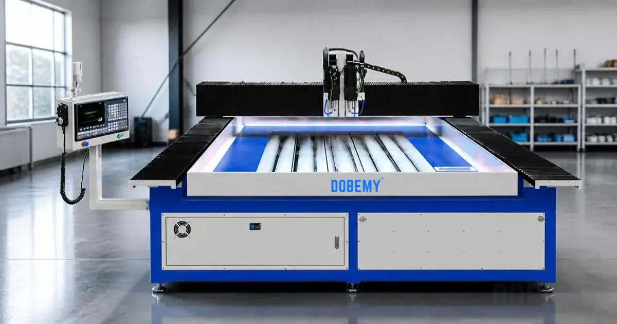
Ready to evaluate CNC tapping for your electrical enclosure production? Send DOBEMY your enclosure drawing, material type and thickness, thread sizes, hole count, and batch target. Our team will review your application and recommend a machine configuration that fits your parts.