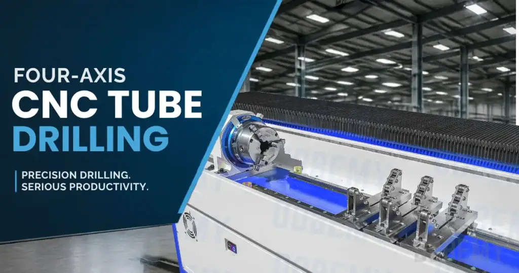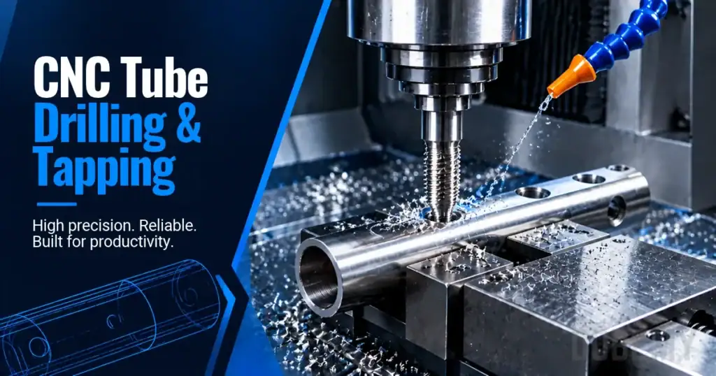


Inclined hole drilling presents unique challenges that make it significantly more complex than drilling into flat surfaces. When a drill enters an angled or irregular surface, the resulting uneven cutting forces can push the tool off location, distort the hole profile, and reduce accuracy. Understanding these mechanisms helps factory owners and engineers select appropriate equipment and develop reliable processes.
Key Takeaways
- Inclined surfaces cause uneven cutting forces because only part of the drill engages initially
- Tool deflection and wandering increase with entry angle and drill overhang
- Intermittent cutting during angled entry creates vibration and accelerates tool wear
- Proper machine setup, tooling selection, and parameter adjustment reduce positioning errors
- Entry strategies like spot drilling or milling a flat improve hole accuracy
inclined hole drilling: The Fundamental Problem of Uneven Cutting Forces
Related guidance: Burr-Free Micro Drilling in Stainless Steel: Process Checklist.
When a drill contacts an inclined surface, only one side of the cutting edge engages the material initially. This partial engagement creates asymmetric cutting forces that push the drill sideways rather than allowing it to cut straight down. The drill experiences radial forces that conventional point geometries cannot resist effectively.
Consider a standard 118-degree twist drill approaching a surface inclined at 15 degrees. The lower cutting edge contacts the workpiece first while the upper edge remains in air. This creates several immediate problems:
- The engaged cutting edge experiences full cutting load while the opposite edge cuts nothing
- Radial forces push the drill toward the lower side of the incline
- The drill point cannot self-center as it would on a flat surface
- Chip formation becomes irregular and evacuation paths change
These uneven forces continue until the full drill diameter engages the material. During this transition period, the drill may wander from its programmed position, creating location errors that compound throughout the hole depth.
Intermittent Cutting and Vibration Issues
Inclined entry transforms smooth drilling into an intermittent cutting process. As the drill rotates, cutting edges repeatedly enter and exit the material during each revolution. This interrupted cutting pattern generates vibration that affects both tool life and hole quality.
The severity of intermittent cutting depends on several factors:
- Entry angle: Larger angles create longer periods of interrupted cutting
- Drill diameter: Larger drills take more revolutions to fully engage
- Spindle speed: Higher speeds increase the frequency of cutting interruptions
- Tool geometry: Point angle and helix angle affect engagement characteristics
Vibration from intermittent cutting causes multiple problems. Tool holders may lose grip on the drill shank. Cutting edges chip or fracture from repeated impact loads. The workpiece may shift in its fixture if clamping force is insufficient. Machine spindle bearings experience additional stress that can affect long-term accuracy.
Tool Deflection and Positioning Accuracy
Tool deflection becomes more severe during inclined drilling because lateral forces act on an extended, unsupported tool length. The relationship between deflection and drilling parameters follows predictable patterns that help engineers plan appropriate processes.
Factors Affecting Drill Deflection
| Factor | Impact on Deflection | Recommended Response |
|---|---|---|
| Length-to-diameter ratio | Deflection increases with the cube of unsupported length | Use shortest drill possible; consider stub drills |
| Entry angle | Larger angles create stronger lateral forces | Reduce feed rate; consider pilot operation |
| Material hardness | Harder materials generate higher cutting forces | Select carbide drills; optimize geometry |
| Drill wear | Worn edges increase cutting forces | Monitor tool life; replace before excessive wear |
| Spindle runout | Runout amplifies deflection effects | Check and correct spindle/holder/collet condition |
When length-to-diameter ratios exceed 5:1, deflection control becomes critical. Some shops use guided drilling bushings or steady rests to support long drills. Others break deep holes into multiple operations using progressively longer drills.
Entry and Exit Challenges
Both entry and exit present unique challenges during inclined drilling. Entry problems focus on positioning and initial engagement. Exit problems involve breakthrough damage, burr formation, and potential drill breakage.
Entry Strategies for Different Angles
Surface angles below 5 degrees typically allow direct drilling with reduced feed rates. The drill can usually establish position before significant wandering occurs. Feed rates should be reduced to approximately one-third of normal until full engagement.
Angles between 5 and 10 degrees benefit from preparatory operations:
- Create a spot drill mark using a drill with matching or larger point angle
- Start with a short, rigid pilot drill to establish location
- Use a center drill to create a conical starting point
- Consider a flat-bottom drill for initial positioning
Angles exceeding 10 degrees often require milling a small flat before drilling. The flat provides a perpendicular surface for drill entry, eliminating the uneven force problem. The flat diameter should be at least 1.5 times the drill diameter to ensure stable engagement.

Managing Breakthrough and Exit Burrs
Inclined exit surfaces create asymmetric breakthrough conditions. One side of the drill exits while the other continues cutting. This produces several problems:
- Uneven burr formation requiring additional deburring operations
- Potential drill grabbing or sudden feed increase
- Risk of drill breakage from bending loads
- Chip packing in partially broken-through areas
Reducing feed rate during exit helps control these issues. Some operations use pecking cycles that fully retract the drill as it approaches breakthrough. Others program dwelling or reduced-feed zones based on calculated exit depth.
Machine Capability Requirements
Machine selection significantly affects inclined drilling success. While 3-axis machines can drill inclined holes, additional capabilities simplify the process and improve results.
3-Axis Machine Limitations
Standard 3-axis machines require creative fixturing to present inclined surfaces appropriately. Options include:
- Angled fixture blocks that orient the part surface perpendicular to the spindle
- Sine plates or adjustable-angle vises for variable positioning
- Custom fixtures designed for specific part geometries
- Multiple setups to access different hole angles
Each setup change adds time and introduces potential positioning errors. Part removal and re-clamping can accumulate tolerance stack-up that affects hole-to-hole relationships.
Benefits of Multi-Axis Machines
Machines with rotary axes or full 5-axis capability can orient the spindle normal to inclined surfaces. This eliminates the fundamental problem of angled entry. Benefits include:
- Direct perpendicular drilling without special fixtures
- Single setup for multiple hole angles
- Improved accuracy from reduced setup changes
- Access to complex angular relationships
- Shorter tool lengths due to better access angles
The decision between 3-axis and multi-axis equipment depends on production volume, part complexity, tolerance requirements, and available capital. High-mix, low-volume shops may not justify 5-axis investment for occasional inclined holes. High-volume production of complex parts often demands multi-axis capability.
Cutting Parameter Adjustments
Successful inclined drilling requires systematic parameter adjustments based on entry angle, material, and tool configuration. Standard cutting data assumes perpendicular entry and must be modified for angled surfaces.
Speed and Feed Modifications
Entry into surfaces angled 2-5 degrees requires feed reduction to approximately one-third of the standard rate. This continues until the full drill diameter engages. Spindle speed may also need reduction to maintain appropriate chip load despite the lower feed rate.
For 5-10 degree angles, consider these adjustments:
- Reduce both speed and feed by 30-50% during entry
- Program ramped feed rates that gradually increase after engagement
- Use high-pressure coolant to assist chip evacuation
- Monitor spindle load to detect excessive forces
Angles beyond 10 degrees should prompt reconsideration of the entire approach. Milling a flat or using specialized tooling often proves more reliable than attempting direct drilling at extreme angles.
Pecking and Chip Control
Pecking cycles become more important during inclined drilling because chip evacuation paths change. Chips tend to pack on the lower side of inclined holes where gravity and coolant flow create accumulation zones.
Effective pecking strategies include:
- Shorter peck depths than standard drilling
- Full retraction pecks to clear chips completely
- Increased dwell time at the bottom of each peck
- Coolant flush cycles between pecks
- Reduced pecking depth as hole depth increases
Tool Selection for Inclined Surfaces
Drill geometry significantly affects inclined drilling performance. While standard drills can work with appropriate parameter adjustments, specialized geometries offer advantages for challenging applications.
Flat-Bottom Drills
Flat-bottom drills with 180-degree point angles excel at inclined surface entry. Without a conventional point, these drills generate primarily axial forces rather than radial forces. This reduces the tendency to wander or deflect during initial engagement.
Applications for flat-bottom drills include:
- Direct drilling into curved or spherical surfaces
- Creating flat-bottom holes without secondary operations
- Starting holes on irregular cast or forged surfaces
- Drilling across existing holes or slots
The trade-off involves reduced self-centering capability and potentially slower penetration rates. Flat-bottom drills typically require spot drilling or bushing guidance for accurate positioning.
Large Point Angle Drills
Drills with point angles of 135-140 degrees offer a compromise between conventional and flat-bottom geometries. The larger point angle reduces the radial force component while maintaining some self-centering ability.
These drills work well for:
- Moderate incline angles up to 10 degrees
- Materials that work-harden easily
- Applications requiring good chip breaking
- Holes with length-to-diameter ratios under 5:1
Workholding and Rigidity Considerations
Secure workholding becomes critical during inclined drilling because lateral forces try to shift the part. Standard clamping that works for perpendicular drilling may prove inadequate when drilling at angles.
Clamping Force Requirements
Calculate required clamping force based on:
- Maximum lateral cutting force from the inclined entry
- Safety factor for interrupted cutting and vibration
- Friction coefficient between part and fixture surfaces
- Number and position of clamping points
Parts should be supported close to the drilling location to minimize deflection. Thin-walled parts may require backing support to prevent distortion or breakthrough damage.
Fixture Design Principles
Effective fixtures for inclined drilling incorporate several design elements:
- Positive location: Use pins, stops, or nests to prevent lateral movement
- Distributed clamping: Multiple clamps share the load and reduce distortion
- Vibration damping: Add mass or damping materials to reduce resonance
- Chip clearance: Design channels for chip flow away from the cutting zone
- Coolant delivery: Direct coolant to the cutting zone through fixture passages
Quality Control and Inspection
Inclined holes require careful inspection because multiple error sources can affect final quality. Standard go/no-go gauges may not work for angled holes, requiring alternative measurement methods.
Common Defects in Inclined Holes
| Defect Type | Probable Cause | Inspection Method |
|---|---|---|
| Location error | Drill wandering during entry | Coordinate measuring machine (CMM) |
| Oval shape | Tool deflection or vibration | Bore gauge at multiple depths |
| Incorrect angle | Setup error or part movement | Angle gauge or CMM |
| Oversize diameter | Drill runout or wear | Pin gauges or bore micrometers |
| Poor surface finish | Vibration or incorrect parameters | Surface roughness tester |
| Excessive burrs | Exit breakthrough control | Visual or deburring gauge |
Process Validation Steps
Before production, validate the inclined drilling process through:
- First article inspection using CMM or optical comparator
- Capability study measuring multiple holes across several parts
- Tool life testing to establish replacement intervals
- Cutting force monitoring to detect process changes
- Statistical process control (SPC) charting of critical dimensions
Document successful parameters including speeds, feeds, tool specifications, coolant settings, and fixture details. This information becomes the baseline for future production and troubleshooting.
Troubleshooting Guide for Common Problems
When inclined drilling problems occur, systematic troubleshooting identifies root causes and corrective actions. Start with the most likely causes based on the observed symptoms.
Drill Wandering or Walking
If the drill moves away from the programmed location during entry:
- Verify the spot drill or pilot hole depth and diameter
- Check drill point geometry and sharpness
- Reduce entry feed rate further
- Consider milling a flat if angle exceeds 10 degrees
- Inspect spindle runout and tool holder condition
Rapid Tool Wear
When drills wear faster than expected:
- Confirm cutting parameters match the material and coating
- Check coolant concentration and delivery pressure
- Measure actual versus programmed spindle speed
- Verify the workpiece material hardness
- Consider upgrading to carbide or coated tools
Vibration and Chatter
If vibration affects hole quality:
- Shorten tool overhang by using stub-length drills
- Reduce spindle speed while maintaining chip load
- Improve workpiece clamping and support
- Check for machine resonance at current parameters
- Add pecking cycles to break chips
Advanced Strategies for Complex Applications
Some applications require combinations of techniques to achieve acceptable results. Complex parts with multiple inclined holes at different angles may benefit from hybrid approaches.
Sequential Operations Approach
Break difficult inclined holes into multiple operations:
- Milling preparation: Create a flat or pocket at the hole location
- Spot drilling: Establish accurate position with a rigid spot drill
- Pilot drilling: Use a short drill to create a guide hole
- Finish drilling: Complete the hole with the final diameter drill
- Reaming or boring: Achieve final size and surface finish if required
This approach takes more time but provides better control over each aspect of hole quality. The additional operations may be justified for high-value parts or critical features.
Specialized Tooling Solutions
Custom or specialized tools can solve specific inclined drilling challenges:
- Step drills: Combine pilot and final diameter in one tool
- Guided drill bushings: Support the drill close to the workpiece
- Adjustable-angle heads: Allow spindle orientation without a 5-axis machine
- Indexable insert drills: Provide consistent geometry as inserts wear
- Through-coolant drills: Improve chip evacuation in deep holes
Evaluate tooling costs against production volume and quality requirements. Specialized tools may have longer lead times but can dramatically improve process capability.
Economic Considerations
The complexity of inclined drilling affects production economics through multiple factors. Understanding these cost drivers helps justify equipment and process decisions.
Direct Cost Factors
- Cycle time: Reduced parameters and additional operations increase machining time
- Tool life: Accelerated wear requires more frequent tool changes
- Scrap rate: Higher probability of quality issues increases material waste
- Setup time: Complex fixtures and alignment procedures add non-cutting time
- Programming time: CAM programming and simulation take longer for inclined features
Investment Justification
When evaluating equipment upgrades for inclined drilling capability, consider:
- Current volume of parts requiring inclined holes
- Projected growth in complex part requirements
- Cost of outsourcing versus in-house capability
- Quality improvements from better equipment
- Setup reduction from multi-axis capability
Calculate the total cost per hole including all operations, tooling, quality control, and potential rework. Compare this with alternative methods or equipment to identify the most economical approach for your production mix.
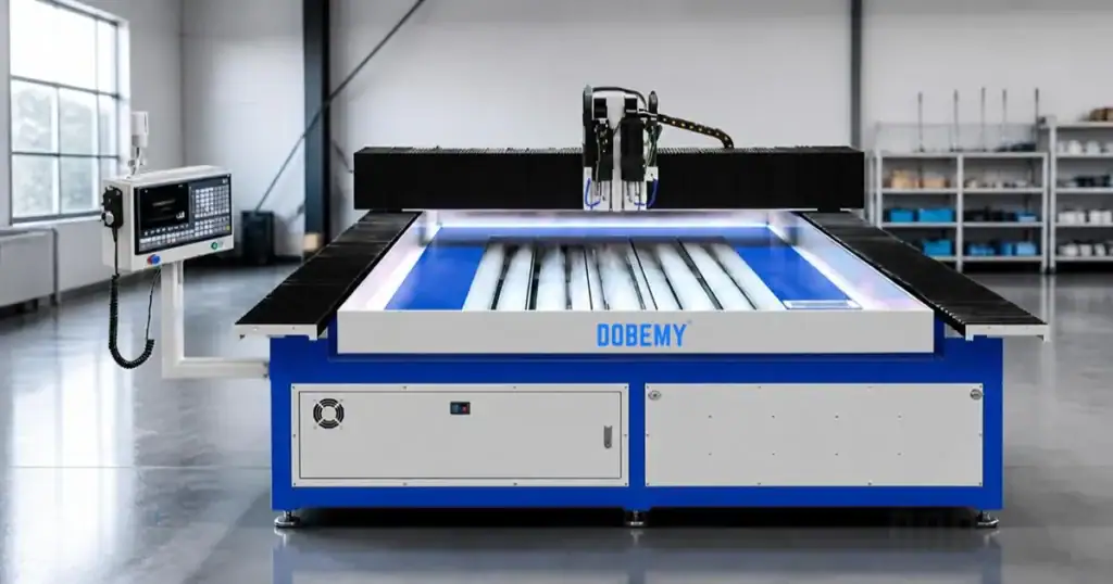
Need help selecting equipment for inclined hole drilling applications? Send DOBEMY your part drawings with material specifications, hole sizes, thread requirements, and production volumes. Our engineering team will review your inclined drilling challenges and recommend appropriate machine configurations, tooling strategies, and process parameters for reliable production.