

Micro drilling machine 0.1mm capability represents a critical threshold in precision manufacturing. When your production requires holes between 0.1mm and 3mm diameter, standard drilling equipment often produces excessive burrs, oversized holes, or broken tools. This guide examines the equipment specifications, tooling requirements, and process controls needed for consistent micro drilling results in production environments.
Key Takeaways
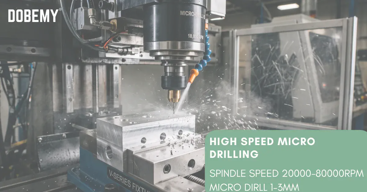
- Micro drilling requires high spindle speeds (20,000-80,000 RPM) and precise runout control under 3 microns
- Tool selection depends on hole diameter, depth-to-diameter ratio, and material hardness
- Peck drilling cycles prevent chip packing and reduce heat buildup in small holes
- Proper coolant delivery and chip evacuation are essential for burr control
- Workholding rigidity and vibration damping directly affect hole quality
Understanding Micro Drilling Requirements
Related guidance: Can Automatic Loading/Unloading Systems Be Added? Achieving Full Automated Produ.
Micro drilling differs fundamentally from conventional drilling operations. The small tool diameters create unique challenges in chip evacuation, heat dissipation, and tool deflection. A 0.5mm drill bit has approximately 400 times less cross-sectional area than a 10mm drill, making it far more susceptible to breakage from lateral forces or chip packing.
The cutting mechanics change significantly at micro scales. Surface finish variations that are negligible in larger holes become critical defects in micro holes. A 5-micron burr represents only 0.05% of a 10mm hole diameter but becomes 5% of a 0.1mm hole diameter. This scale difference demands different approaches to tool selection, machine configuration, and process control.
Material behavior also shifts at micro scales. Work hardening effects concentrate in smaller zones around micro holes. Thermal effects become more pronounced because the reduced tool mass cannot absorb and dissipate heat effectively. These factors combine to make micro drilling one of the most challenging metalworking operations.
Production environments face additional challenges beyond laboratory conditions. Maintaining consistent quality across thousands of holes requires robust process control. Temperature variations throughout the day affect machine accuracy and tool performance. Operator skill becomes critical when handling tools that are barely visible to the naked eye.
Spindle Speed and Feed Rate Considerations
High spindle speeds are essential for micro drilling operations. The cutting speed formula (RPM = cutting speed × 1000 / π × diameter) shows that maintaining proper cutting speeds for small diameters requires exponentially higher RPMs. While a 10mm drill might operate at 1,000 RPM in aluminum, a 0.1mm drill needs theoretical speeds approaching 100,000 RPM for the same cutting speed.
Most micro drilling applications operate between 20,000 and 80,000 RPM, depending on:
- Tool diameter and material
- Workpiece material properties
- Hole depth requirements
- Available coolant delivery methods
- Machine spindle capabilities
Feed rates require careful balance. Too slow causes rubbing and work hardening. Too fast causes immediate tool breakage. The feed per revolution typically ranges from 0.5% to 2% of the drill diameter. For a 0.5mm drill, this means feeds between 0.0025mm and 0.01mm per revolution.
Acceleration and deceleration control becomes critical at high speeds. Sudden speed changes create inertial forces that can snap micro drills instantly. Modern CNC controllers use S-curve acceleration profiles to minimize these forces during rapid moves and drilling cycles. The acceleration ramp time should be at least 0.5 seconds for spindle speeds above 40,000 RPM.
Selecting the Right Micro Drilling Machine 0.1mm System
Related guidance: Troubleshooting Tap Breakage in CNC Drilling and Tapping Production.
Choosing appropriate equipment for micro drilling requires evaluating multiple factors beyond basic spindle speed. The machine structure must provide exceptional rigidity and thermal stability. Even small thermal expansions can cause position errors exceeding hole tolerances.
Key machine specifications to evaluate include:
- Spindle runout at operating speed (not just static)
- Positioning accuracy and repeatability
- Thermal compensation capabilities
- Vibration isolation features
- Controller resolution and response time
- Available tool holding systems
- Coolant delivery options
Air bearing spindles offer the best performance for ultra-precision micro drilling. These spindles achieve runout values below 1 micron and can operate at speeds exceeding 100,000 RPM. However, they require clean, dry compressed air and have limited torque compared to conventional bearings.
Tool Selection for Different Hole Sizes
0.1mm to 0.5mm Range
This range requires specialized micro drills with specific geometry features:
- Single-flute designs for maximum core strength
- Carbide grades with fine grain size (0.2-0.5 microns)
- Point angles between 90° and 118° for centering stability
- Specialized coatings like diamond-like carbon (DLC) for friction reduction
Tool holders must provide exceptional concentricity. Standard collets often exceed acceptable runout limits for micro drilling. Hydraulic or shrink-fit holders typically achieve the required 3-micron runout tolerance. The tool shank diameter affects rigidity significantly. Larger shanks reduce deflection but limit minimum hole size.
0.5mm to 1.0mm Range
This intermediate range allows more tool options:
- Two-flute designs become viable for better chip evacuation
- Standard 118° or 135° point angles work for most materials
- TiAlN or AlCrN coatings improve tool life
- Stepped shank designs provide better rigidity
Peck drilling cycles become essential in this range. The increased hole depth relative to diameter creates chip evacuation challenges. Pecking depths typically range from 0.5 to 1.5 times the drill diameter. Each peck must fully retract to clear chips effectively.
1.0mm to 3.0mm Range
Larger micro drills offer more flexibility:
- Standard drill geometries work for many applications
- Three-flute designs possible for aluminum and soft materials
- Through-coolant drills improve chip evacuation
- Variable helix designs reduce vibration
This range bridges micro and conventional drilling. Machine selection depends more on precision requirements than pure size constraints. Many high-precision CNC machines can handle this range effectively with proper tooling and parameters.
Machine Configuration Comparison
Related guidance: Flow Drilling vs Conventional Drilling for Thin Wall Metal Parts: Complete Chip-.
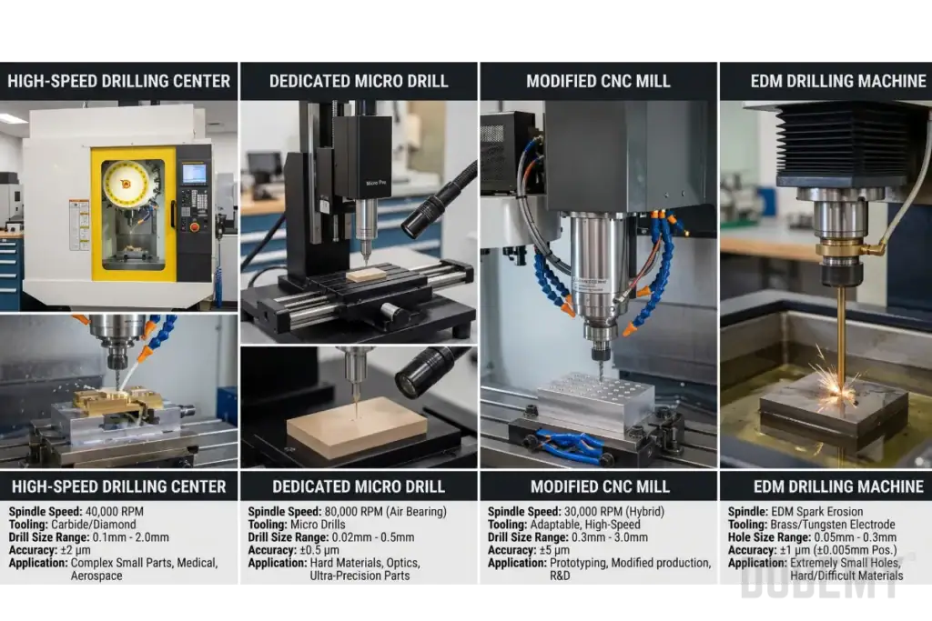
| Feature | High-Speed Drilling Center | Dedicated Micro Drill | Modified CNC Mill | EDM Drilling |
|---|---|---|---|---|
| Max Spindle Speed | 40,000 RPM | 80,000 RPM | 20,000 RPM | N/A |
| Runout Control | 5 microns | 2 microns | 10 microns | Zero |
| Minimum Hole Size | 0.3mm | 0.05mm | 0.5mm | 0.1mm |
| Depth Capability | 20×D | 30×D | 15×D | 100×D |
| Burr Formation | Moderate | Low | High | None |
| Setup Complexity | Medium | High | Low | High |
| Operating Cost | Medium | High | Low | Very High |
| Best Application | General precision | Ultra-precision | Prototype/low volume | Hardened materials |
Coolant and Chip Evacuation Strategies
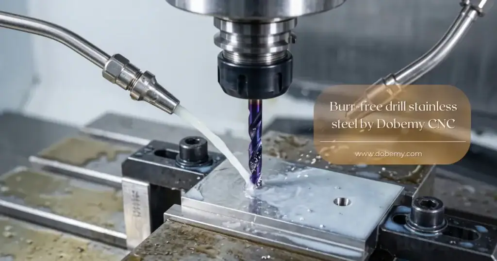
Effective coolant delivery determines success in micro drilling. The small tool diameter and deep holes create challenging conditions for coolant penetration. Standard flood coolant often cannot reach the cutting zone effectively.
Through-spindle coolant (TSC) provides the most effective delivery for holes above 0.5mm diameter. The coolant flows through the tool center, directly reaching the cutting edges and forcing chips up the flutes. TSC pressure must be carefully controlled to avoid hydraulic forces that could break the tool.
For holes below 0.5mm, through-tool coolant becomes impractical due to tool strength limitations. Alternative methods include:
- Minimum quantity lubrication (MQL) with precisely metered oil mist
- Pulsed air blast between pecking cycles
- Ultrasonic-assisted coolant delivery
- Cryogenic cooling for specific materials
Chip evacuation relies on proper pecking cycles. Each peck must fully retract above the workpiece surface to clear chips. Dwell times at the bottom of each peck allow coolant penetration and chip breaking. The pecking sequence typically follows this pattern:
- Rapid approach to 0.5mm above the previous depth
- Feed at programmed rate for one peck increment
- Dwell for 0.1-0.5 seconds
- Rapid retract to clearance height
- Dwell for chip clearing
- Repeat until final depth
Workholding and Vibration Control
Related guidance: CNC Drilling and Tapping Machine Buyer Guide: Complete Selection Criteria for Fa.
Micro drilling demands exceptional workholding rigidity. Even microscopic workpiece movement causes drill wander, oversized holes, or tool breakage. The workholding system must resist both cutting forces and high-frequency vibrations from the spindle.
Vacuum chucks provide excellent holding for flat workpieces without distortion. The distributed holding force prevents localized stress that could deflect thin materials. For irregular shapes, soft-jaw vises with precision-ground clamping surfaces minimize workpiece deflection.
Vibration damping becomes critical at high spindle speeds. Sources of vibration include:
- Spindle bearing resonances
- Tool holder imbalance
- Floor vibrations from nearby equipment
- Coolant pump pulsations
- Servo motor oscillations
Passive damping using polymer or composite machine bases reduces transmitted vibrations. Some machines use active vibration cancellation systems that detect and counteract vibrations in real-time. Tool holders with built-in damping elements also help reduce vibration transmission to the cutting edges.
The machine foundation plays a crucial role in vibration control. Isolated concrete pads or pneumatic leveling feet prevent ground vibrations from affecting the drilling process. Environmental vibration surveys help identify problematic frequencies before installation.
Material-Specific Drilling Parameters
Aluminum Alloys
Aluminum’s low hardness and high thermal conductivity make it relatively easy to micro drill. However, built-up edge formation and chip adhesion create challenges. Key considerations include:
- Sharp cutting edges with polished flutes
- Alcohol-based coolants to prevent chip welding
- Higher feed rates to prevent rubbing
- Single-flute drills for holes under 0.3mm
The specific alloy affects drilling parameters significantly. Series 2000 and 7000 alloys contain copper and zinc that improve machinability. Series 1000 pure aluminum tends to be gummy and requires sharper tools with increased rake angles.
Stainless Steel
Stainless steel work hardens rapidly during micro drilling. The austenitic grades (304, 316) are particularly challenging due to their high work hardening rate. Successful strategies include:
- Consistent feed rates without dwelling
- Sulfur or chlorine-based cutting fluids
- Reduced cutting speeds compared to carbon steel
- Frequent tool changes before excessive wear
Ferritic and martensitic grades machine more easily but still require careful parameter control. The chromium content creates hard carbides that accelerate tool wear. Premium coatings like AlTiN or nanocomposite structures extend tool life in these materials.
Hardened Steel
Drilling hardened steel above 45 HRC requires specialized approaches. Carbide micro drills can handle materials up to 55 HRC with proper parameters. Beyond this hardness, EDM drilling becomes more practical. For carbide drilling:
- Use premium nano-grain carbide tools
- Reduce speeds by 50% compared to soft steel
- Minimize peck depth to prevent tool deflection
- Consider pilot holes with EDM for critical features
Tool geometry modifications help in hard materials. Reduced helix angles provide more strength. Thicker web designs resist deflection. Special point geometries with reinforced cutting edges survive the high stresses better than standard designs.
Plastics and Composites
Non-metallic materials create different challenges. Plastics can melt and adhere to tools. Composites cause rapid tool wear from abrasive fibers. Successful approaches include:
- Diamond-coated tools for composites
- Air cooling for heat-sensitive plastics
- Higher speeds with reduced feeds
- Backing material to prevent exit burrs
Each plastic type requires specific parameters. Acrylic drills cleanly with sharp tools and proper speeds. Polycarbonate tends to grab tools and requires reduced rake angles. PTFE and other fluoropolymers need extremely sharp edges and minimal heat generation.
Pre-Drilling Checklist for Micro Drilling Operations
Related guidance: Drilling and Tapping Machinery for HVAC and Heat Exchanger Manufacturing.
Before starting micro drilling operations, verify these critical items:
• Tool inspection: Check drill point condition under magnification for chips or wear
• Runout measurement: Verify total indicated runout (TIR) at operating speed is within specification
• Coolant system: Confirm pressure, flow rate, and concentration meet requirements
• Workpiece fixturing: Test clamping rigidity and verify no workpiece movement
• Program verification: Review feed rates, speeds, and pecking cycles for the specific material
• Machine warm-up: Run spindle warm-up cycle to stabilize thermal conditions
• First article inspection: Plan measurement method for initial hole verification
• Tool life tracking: Set counter limits based on material and hole specifications
Quality Control and Inspection Methods
Inspecting micro holes requires specialized metrology equipment. Standard pin gauges and optical comparators lack the resolution for accurate measurement. Common inspection methods include:
Optical Measurement Systems: Video measuring machines with high-magnification optics measure hole diameter, position, and roundness. Edge detection algorithms identify hole boundaries with sub-micron accuracy.
Contact Probing: Micro probes with tip diameters down to 0.1mm physically measure hole geometry. The probe deflection indicates hole size and form errors.
CT Scanning: Industrial computed tomography provides non-destructive internal inspection. This method reveals burrs, cracks, or debris inside blind holes that other methods cannot detect.
Replica Molding: Silicone rubber compounds create negative impressions of micro holes. The replicas can be sectioned and measured under microscopes to evaluate surface finish and burr formation.
Quality control must address several critical parameters:
- Hole diameter tolerance (typically ±0.01mm or tighter)
- Position accuracy relative to datum features
- Perpendicularity to the surface
- Surface roughness inside the hole
- Burr height at entry and exit
- Presence of recast layer or heat-affected zone
Statistical process control (SPC) helps maintain consistent quality in production. Track key measurements like hole diameter and position across multiple parts. Control charts identify process drift before parts fall out of specification.
Troubleshooting Common Micro Drilling Problems
Excessive Burr Formation
Burrs at hole entry and exit reduce part quality and require secondary operations. Common causes include:
- Dull cutting edges causing material push rather than cutting
- Incorrect point angle for the material
- Insufficient backing support at hole exit
- Excessive feed rate in the final breakthrough
Review your tool condition first. Even slight edge wear significantly increases burr formation in micro drilling. Check the drill point under magnification for chipping or rounding. Consider reducing the feed rate for the last 0.1mm of drilling depth to minimize exit burrs.
Oversized or Tapered Holes
Dimensional errors often result from:
- Excessive runout in the spindle or tool holder
- Tool deflection from side forces
- Incorrect speeds causing tool vibration
- Chip re-cutting enlarging the hole
Measure spindle runout at operating speed, not just statically. Dynamic runout often exceeds static measurements due to bearing clearances and thermal growth. Verify that pecking cycles fully evacuate chips before re-entering the hole.
Frequent Tool Breakage
Micro drill breakage disrupts production and risks workpiece damage. Investigation should examine:
- Sudden feed rate changes or acceleration spikes
- Chip packing in flutes
- Coolant interruption during drilling
- Workpiece movement or vibration
Check the CNC program for smooth motion profiles. Verify that rapid positioning moves include adequate clearance above the workpiece. Confirm coolant pressure remains consistent throughout the drilling cycle.
Poor Hole Position Accuracy
Position errors accumulate from multiple sources:
- Thermal drift in machine axes
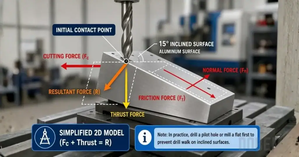
- Tool deflection during entry
- Workpiece datum errors
- Incorrect tool length compensation
Implement warm-up cycles before precision operations. Consider spot drilling with a larger, rigid tool before micro drilling. Verify workpiece alignment and datum surfaces meet specified tolerances.
Ready to implement micro drilling in your production? Send DOBEMY your technical drawing with material specifications, hole sizes from 0.1mm to 3mm, thread requirements if applicable, and monthly batch quantities. Our application engineers will review your requirements and recommend the optimal micro drilling configuration for your specific needs.